 BuildCAD
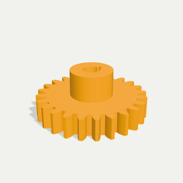
Build a gear with dimensions you understand
How do I generate an involute spur gear?
Set tooth count and module, followed by face width, bore diameter and hub dimensions. Select Generate model to rebuild the solid. Rotate the preview to inspect teeth, bore and hub before choosing STEP or STL.
This external spur gear has a fixed 20° pressure angle and keyed bore. The actual default model uses 24 teeth, module 2, 10 mm face width, 8 mm bore and a 20 mm hub rising 12 mm. Rebuilds use no AI credits.
How do module and tooth count affect gear size?
Module sets metric tooth size. For a standard unshifted gear, pitch diameter d = m × z: module times tooth count. Outside diameter is m × (z + 2). Module 2 with 24 teeth gives a 48 mm pitch diameter and 52 mm outside diameter. The pitch circle is theoretical, rather than the edge measured with calipers.
Increasing module enlarges teeth and diameter. Increasing tooth count at fixed module enlarges diameter while preserving tooth spacing. Supported values are module 1–4 mm in 0.25 mm steps and 12–60 whole teeth. KHK: basic gear terminology and calculations ↗
How do I calculate gear ratio and center distance?
Match module and pressure angle. Nominal center distance = m × (z₁ + z₂) ÷ 2. A module-2 pair with 24 and 48 teeth has pitch diameters of 48 and 96 mm and center distance 72 mm. Driving the larger gear gives a 2:1 speed reduction.
Generate each gear separately and verify the assembly. The formula excludes printing clearance, bearing fit and housing stiffness. This tool does not simulate meshing, calculate contact ratio or optimize backlash. Check hub and bore constraints on both gears. KHK: selecting gear specifications ↗
How large can the gear bore and hub be?
The bore includes a simple keyway, with width equal to the larger of 2 mm and one quarter of bore diameter. These simplified dimensions need checking against your shaft, key and applicable manufacturing requirements.
Hub diameter must be strictly below root diameter − 2 mm, where root diameter = module × (teeth − 2.5). Bore diameter must be strictly below hub diameter − 4 mm. Equality fails. Reducing module or tooth count may require a smaller hub and bore, even when each field is individually within range.
How do face width and hub height affect total thickness?
Face width sets the toothed disk thickness, from 3–30 mm. Hub height adds 0–25 mm above it; total height is their sum. Zero leaves no raised boss. The bore and keyway pass through both.
Allow space for shaft engagement, housing clearance and adjacent bearings. Increasing thickness changes geometry without establishing a torque rating. Record final dimensions alongside assembly measurements.
Should I download STEP or STL for my gear?
Use STEP for assembly checks and CAD edits, or STL for slicing. Both come from the completed solid. After editing, generate again to update the preview and enable downloads with your new dimensions.
Inspect tooth detail and bore in the slicer; test a printed pair slowly by hand before adding a drive. Material, layer direction, manufacturing error and alignment affect performance. Measure a poor fit before revising dimensions: scaling the entire model changes module as well as bore size.
What should I check before using this gear in a transmission?
Sampled involute points form a polygon before extrusion. This supports concept geometry and fit prototypes, without certifying a gear-cutting profile. There is no configurable pressure angle, profile shift, backlash, or helical, internal or bevel gearing. Low tooth counts need particular interference and tooth-root review.
Gear accuracy, fatigue life, noise, allowable torque and manufacturing suitability require separate evaluation of the complete pair, material and operating conditions. The export provides starting geometry for that process.
Parameter reference
These ranges are the limits of the models available in this tool. All dimensions are in millimeters unless shown as a count.
| Parameter | Default | Range and effect |
|---|---|---|
| Teeth | 24 | 12–60 whole teeth; inspect low tooth counts for interference. |
| Module | 2 mm | 1–4 mm in 0.25 mm steps; sets tooth size and pitch diameter. |
| Face width | 10 mm | 3–30 mm in 0.5 mm steps; thickness of the toothed disk. |
| Bore diameter | 8 mm | 3–30 mm in 0.5 mm steps; must be smaller than hub diameter − 4. |
| Hub diameter | 20 mm | 10–60 mm in 1 mm steps; must be smaller than root diameter − 2. |
| Hub height | 12 mm | 0–25 mm in 0.5 mm steps; added above the face width. |
Common questions
Can I change the pressure angle?
It is fixed at 20°. Mating gears need compatible tooth geometry; changing module cannot make a different pressure angle compatible.
Does the generator support a gear pair?
Generate each gear separately using the same module and 20° pressure angle, then inspect the pair in CAD. Use the guide above for nominal center distance.
Why is my hub or bore rejected?
The hub must be more than 2 mm smaller than root diameter; the bore must be more than 4 mm smaller than the hub. Reduce them or increase gear size.
Are these gears certified for transmitting power?
No. Solid checks provide no load rating, gear quality grade or certification. Fit, interference, materials and operating loads require separate evaluation.
Can I download a gear without using AI credits?
Yes. Default samples and numeric rebuilds include STEP and STL without AI-credit usage. Other features requested through the AI workspace follow its normal credit pricing.